
When we first met with Jie, she showed us her remarkable powered sketchbook, which she created by disassembling a Moleskine notebook, hollowing out the back cover to embed a rechargeable battery she repurposed from a cell phone charging case and then running power leads onto each page. Natalie also used this approach to power her wifi-connected notebook.
Both of these hacks seemed far too sophisticated for me to attempt myself when I first saw them, but now I have a lot more paper circuitry projects under my belt. My notebook finally filled up and I needed to move into a new one, so I figured it was time to see if I could up my hacking game and create my own version of Jie’s and Natalie’s power hack.
Disclaimer: Taking electronics apart can be dangerous. Always take proper safety precautions. My fingers definitely got scorched quite a bit throughout the project.
Materials and Tools
- 5v cell phone charging case (I used this one)
- Soldering iron
- Solder
- Soldering wick
- Cardboard
- Copper tape
- Xacto knife and cutting surface
- Wire
- Wire strippers
- Pencil
- Flathead screwdriver
- Pliers (standard; having an extra pair of needle nose pliers is handy, too)
- Multimeter
What I wished I’d had:
- Helping hands (like so)
Process
Step 1 – Open the case
The first step was to take apart the case housing to expose the battery. This was surprisingly difficult because they used glue to keep the two halves of the cell phone case together, so I had to pry it apart at different parts along the seam with a flathead screwdriver. I think if I’d had a heat gun (or a hairdryer), it would have made this much easier. Once I managed to get it open, I took a picture of it before I did anything else so I’d have a visual record of how the components and wires were originally connected.
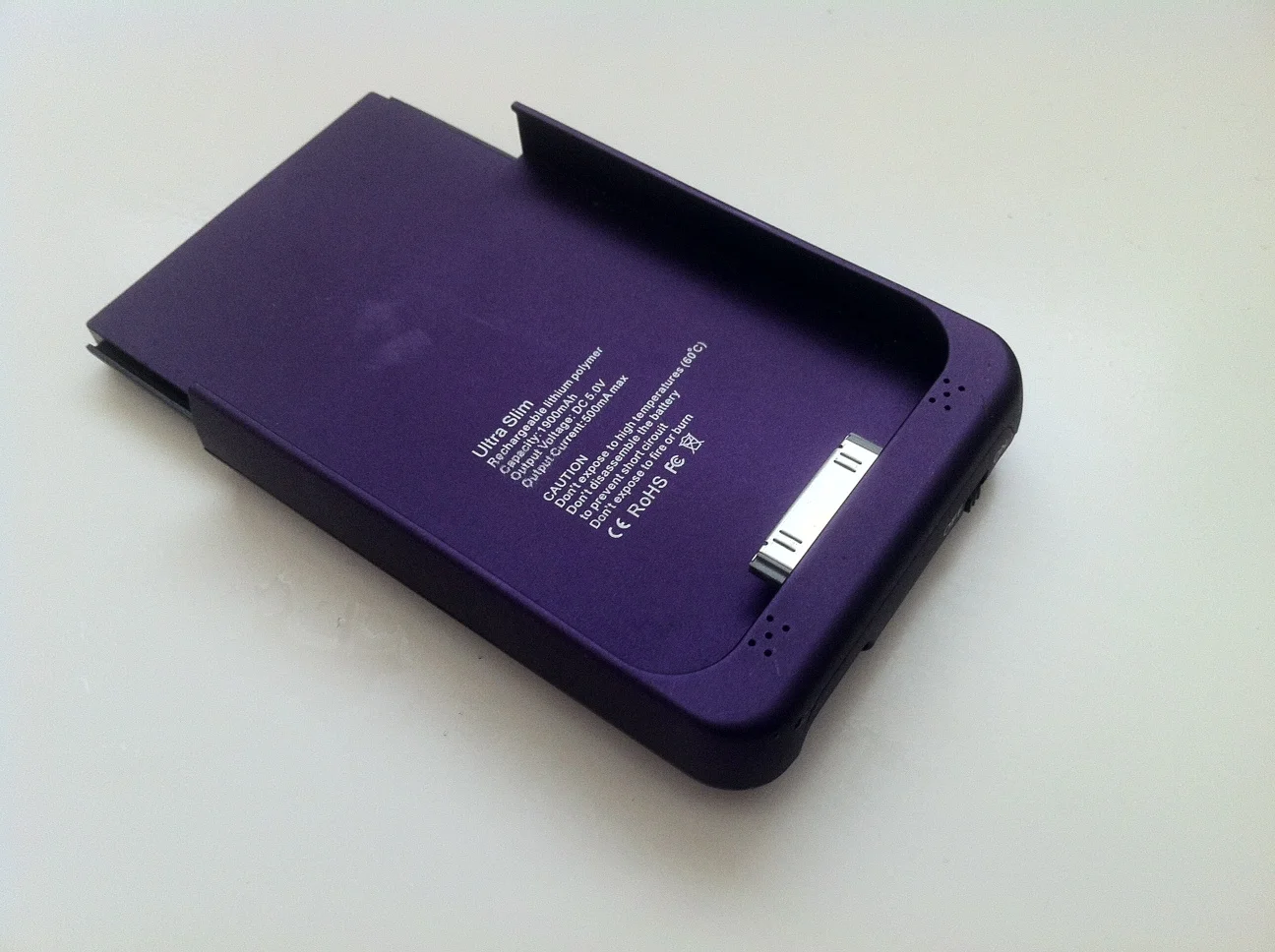
Picture 1a - Case before hacking
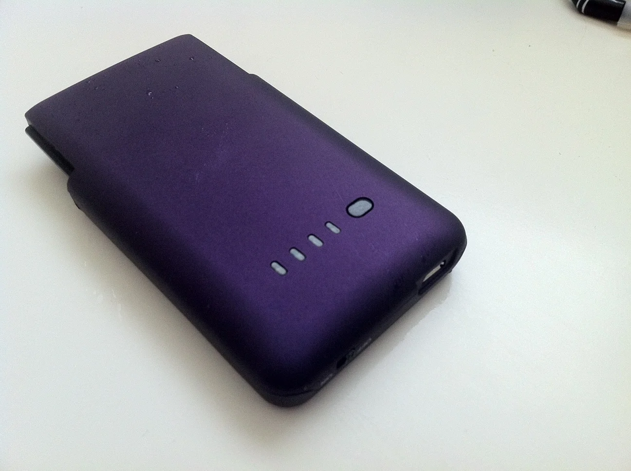
Picture 1b - Back of case
Step 2 – Disconnect the battery
Natalie suggested that I disconnect the battery from the board right away to reduce the chance of running the battery down or shorting it out when working with the board. This model was designed to charge iPhones; the user places their phone on the case and slides it down onto the charging pin. In Picture 2, the bottom of the charging mount is visible. Note the pin-outs: VCC (power in), D-, D+, GND (power out) and D2. (From what I could find online, the D pins handle data exchange so they were unused in this hack.) To make things easier and not strain the wires connecting to the battery, I decided to unsolder both of them. The board was labeled (note the “B+” just below the red wire in Picture 2), but having the photographs of everything hooked up was reassuring. Red often means “hot” or “power” but not always, so it’s always best to document before you start tearing things apart!
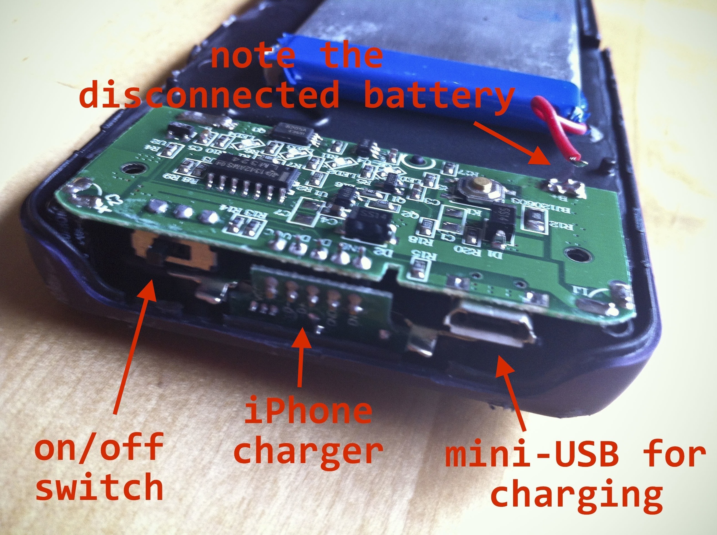
Picture 2
Step 3 – Remove the battery and circuit board from the case
Taking a close, careful look, I realized the board was held in place largely by the phone charging pin, which from this perspective, hooks under the board. In Picture 2, note the two metal tabs on either side of the charging pin mount. These were bent down, so I used pliers lift them up as shown.
The other thing that kept the circuit board in place was the combination of two capacitors mounted to the underside of the board right at each corner of the hard plastic case, which prevented me from being able to simply slide the circuit board down and up out of the case. I went with brute force: I used heavy-duty pliers to tear apart the corners and expose the capacitors (Picture 3). Okay, this was the hardest part. Once that was done, I was able to slide the board down to unhook the phone charging mount.

Picture 3
Step 4 – Remove the phone charging mount
Since I’m not using this to charge a phone anymore, I only needed the power pinouts on the main circuit board: the little break-out board attached to the phone charging mount had to go. I probably could have tried desoldering the pins that connected the break-out board to the primary circuit board, but instead, I just cut the breakout board off with heavy duty wire cutters since I don’t have a desoldering gun.
Step 5 – Design the notebook cover
Once I’d gotten the parts out of the case, I could begin to design the cover that would hold the battery & circuit board. I decided that this would just be a rough prototype so I could get a better understanding of everything involved and practice my soldering skills. Not having really high expectations of clean perfection helped a lot! I’m glad I took this approach because I did make a significant error in judgment, as you’ll find out.
I wanted something slightly smaller than my new notebook that I could attach to the back cover. After measuring and cutting a piece of stiff cardboard, I placed the circuit board on top and marked where the power switch and mini-USB charger inputs would go and cut out notches to accommodate them which can be seen in Picture 4.
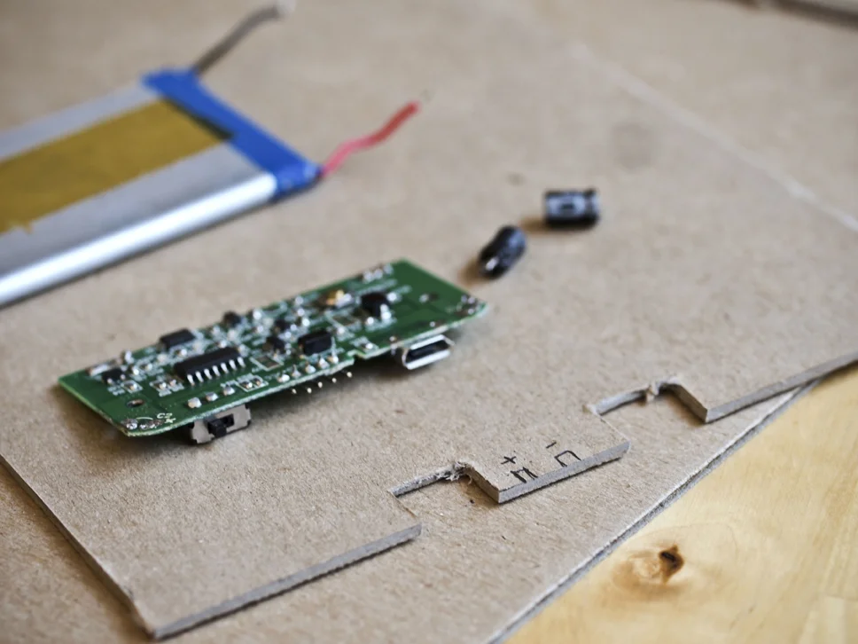
Picture 4
Step 6 – Remove the capacitors
Looking at Natalie’s hack, she managed to get her capacitors to lay flat, which meant desoldering them and reattaching them laying on their sides. The two capacitors are NOT identical, so I made a note of which went where on the circuit board.
And then I made my biggest mistake of the entire project. Learn from me! A couple of important disclosures:
- I am not an experienced electronics hobbyist. My technique is definitely in the developing phase.
- I did not have soldering wick when I started, although I was aware of its existence.
- I should have ordered a set of helping hands when I (eventually) bought my soldering wick.
First, I tried to desolder them by heating the solder on one side and pulling on the capacitor. This would have been ideal as it would have kept the capacitors’ legs as long as possible, making it easier to reattach them so that the capacitors could lay flat. I don’t know if it’s my soldering iron, the kind of solder the factory used when manufacturing the case or some combination of the two, but it was really, really hard to get the solder to re-melt and by the time it did, the board and components were too hot and I’d scorch my fingers. (This is where the helping hands would have been really useful.)
The mistake: I decided to trim the capacitors’ wires as close to the solder join as possible with the theory I’d be able to pull the end free more quickly, before the solder cooled. This would have been workable if I didn’t have to reuse these capacitors or if I wanted to mount them vertically on top of the circuit board.
Sadly, this still didn’t work—I was succeeding in scorching my fingers but not freeing the capacitors. I admitted defeat and ordered soldering wick. (And should have also ordered the helping hands.)
Once the soldering wick arrived, I took another stab at desoldering the capacitors. It took some time, practice and a lot of rookie mistakes (pro tip: remember to expand the soldering wick into as wide a ribbon as possible before attempting to desolder), but eventually, I managed to detach the capacitors (Picture 4).
Step 7 – Planning the circuit traces
I’d already decided where the circuit board would go and cut notches to accommodate the deeper on/off switch and mini-USB input (Step 5), and now I needed to make a couple more design decisions: where the power leads would connect to the cover and where the battery would go (Picture 5).
Picture 5
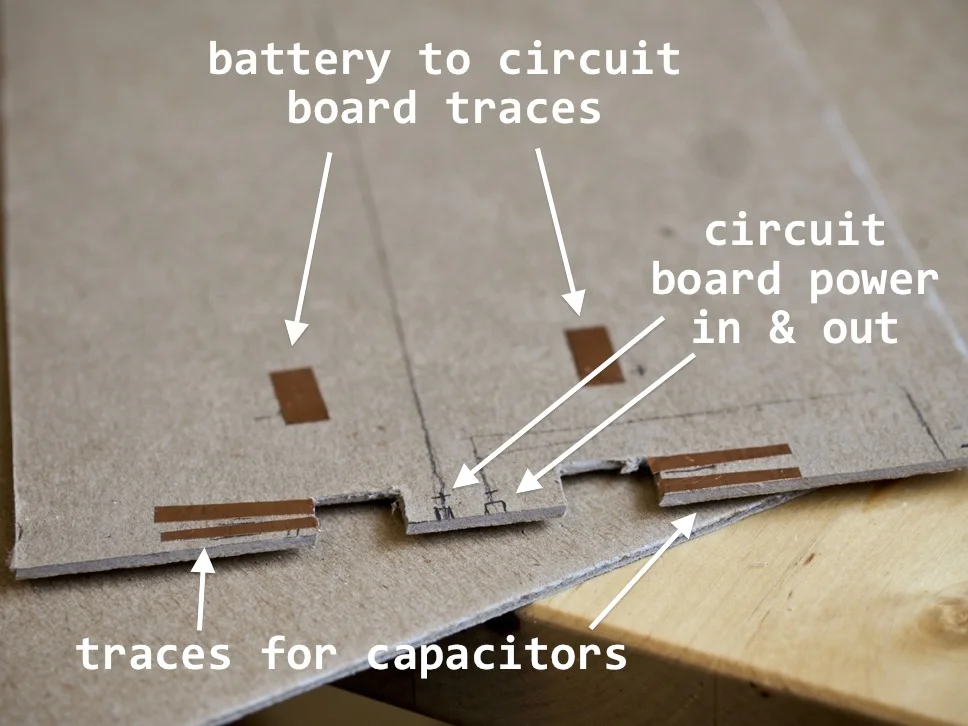
I marked the following locations on the cardboard:
- The circuit board’s power in and out
- The power in and out for both capacitors
- The battery’s power in and out
- NOTE – I can’t remember why I decided to connect the battery to the circuit board via copper tape instead of directly connecting to the circuit board. This step was unnecessary for this particular design and I wouldn’t take this approach again.
I drew lines connecting the circuit board’s power in and out to where I wanted my power leads. Then it was time to put down copper tape circuit traces, which I did in this order:
- Traces for the capacitors (they look like whiskers in Picture 5)
- Traces for the battery-to-circuit board connection (the floating rectangles of tape)
- Traces for the circuit board-to-power leads (can be seen in Picture 7 below)
Picture 6
Picture 7
Re-checking the placement of the circuit board on the cardboard (Picture 6), the on/off switch and mini-USB port are deeper than the cardboard, I realized I’d need to add a couple of cardboard shims to lift the circuit board up so that both the switch and USB would be flush with the bottom of the cardboard (Picture 7).
Picture 8
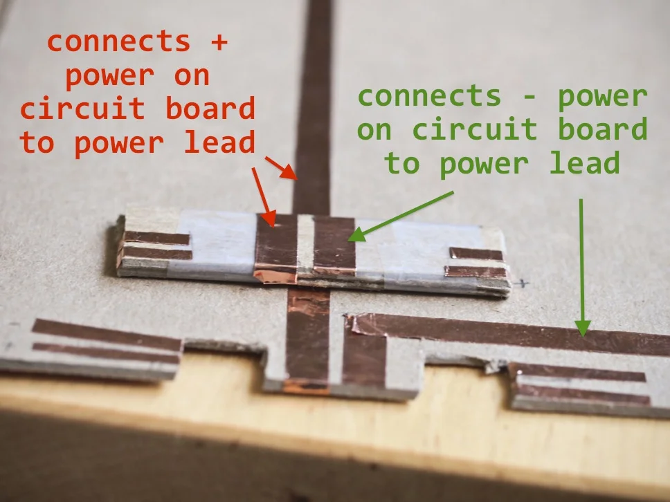
Because the shim would cover the copper traces connecting the circuit board to the power leads as well as the traces for the capacitors, I added copper contacts to the bottom of the shim (Picture 8). I placed the shim copper traces-side down, lined it up with the traces on the base, taped it and tested for continuity with a multimeter. Success! If my prototype didn’t work, it wouldn’t be due to the shim’s contacts.
Step 8 – Hooking up the circuit board to the cover’s power lead traces
To connect the circuit board’s power in and out to the cover, I cut two short pieces of wires, stripped the ends and soldered them to the board and cover (Picture 9). It wasn’t pretty, but it works!
Picture 9
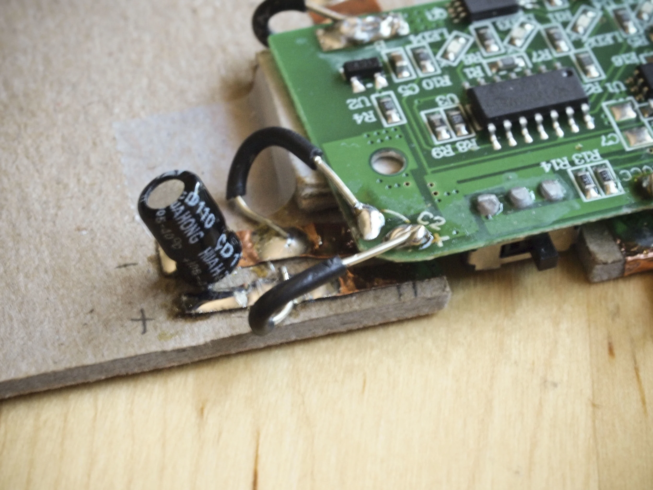
Step 9 – Reconnect the capacitors
Because I snipped off the end of my capacitors when trying to make it easier to desolder them in Step 6, I had to solder them to the cover at an angle (Pictures 10 and 11). This means that my prototype wasn’t as flat as it could have been. Lesson learned! Another set of jumper wires connected the copper traces on the cover to the circuit board.
Picture 10
Picture 11
Step 10 – Reconnect the battery
Again, I don’t know why I didn’t just connect the battery to the circuit board—the wires were long enough for a comfortable connection (Picture 12).
Picture 12
Testing
After everything was wired up, I connected two jumper cables with alligator clip leads to the cover. I had a sewable LED lying around, which made it a perfect tester. I clipped the leads and flipped the switch. Success! (Picture 13)
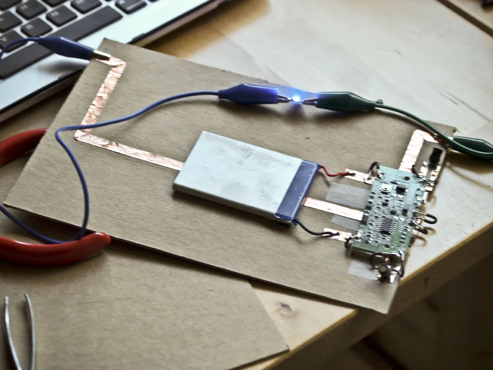
Picture 13
I decided I wanted an easy way to tell if the battery was turned on, so I added one of Jie’s circuit stickers as a status light (Picture 14).
Picture 14
Takeaways
- Setting this up as a practice run made it much easier to accept my own mistakes and less than stellar crafting.
- It would have been less frustrating for me if I’d made to sure to have all of my materials ahead of time—not having soldering wick made things more difficult than it had to be.
- I’d like to find a cleaner way to connect the circuit board power in and out to the cover.
- With more careful planning, I could also incorporate an Arduino Pro mini or a Trinket with clippable pin-outs. I have a couple of 3V Trinkets, so I’ll have to figure out how to step down the voltage from the 5V rechargeable battery.
What ideas do you have? Any suggestions? Share them in the comments!